Lenovo T420 (Maximized)
Table of contents
⚠️ EOL: No microcode updates
This board’s CPU generation has reached End of Servicing Updates. See per-board EOL/ESU status for ESU dates and Heads threat model for security implications.
✅ PROTECTED: TPM GPIO Reset
Pre-Skylake platform — dedicated PLTRST# pin, not GPIO-shared. See Per-Board Protection Status, TPM GPIO Reset Vulnerability.
USB3: no integrated xHCI — see Install an OS → USB3.
Hardware Compatibility
Hardware: t420 — see the Hardware Compatibility List.
⚡ Safety First
Before starting, please read our SPI Programmer Best Practices guide for essential safety information and programmer recommendations.
Disassembly
→ Libreboot T420 external flashing guide (detailed disassembly photos)
→ Lenovo T420 and T420i User Guide
The T420 has a single 8 MB SPI flash chip (Winbond W25Q64CV) that holds the BIOS, ME firmware, and flash descriptor. Unlike the T430 and X230 (which use two separate chips), no ROM splitting is required.
Tools required
- Flat-nose pliers (or sleeve tool for VGA screws)
- Phillips screwdriver (various sizes)
- Small crowbar or spudger (for prying keyboard and bezel)
- CPU thermal grease (for reassembly)
- Spare screws (some may strip during disassembly)
Critical: Remove all batteries (including the CMOS RTC battery) AND disconnect the AC adapter before starting.
Disassembly steps
Full motherboard extraction is required — the T420 is more involved than the T430 because the main board must be separated from the magnesium frame. Budget approximately 30 minutes.
- Bottom covers — Remove the main battery, ultrabay device, and all screws on the black bottom cover.
- Keyboard — Use a small crowbar to push the keyboard gently toward the screen. Lift it and detach the ribbon cable.
- Front cover (palm rest) — Pry up around the sides with a spudger, lift the palm rest off, and disconnect the touchscreen/pointing-stick ribbon cable.
- Internal components:
- Speaker (red screws)
- Modem/telephone jack and WWAN card (pink screws)
- Screen assembly (green screws) — note cable routing for reassembly
- Fan assembly — Disconnect the USB port connections (blue) and remove the fan screws (red).
- Bottom cover — Flip the machine over and remove all visible screws securing the magnesium frame.
- VGA port — The VGA connector screws are unusually tight; loosen with flat-nose pliers or a sleeve tool.
- Main board — Lift the main board carefully off the magnesium frame, checking that no cables remain attached.
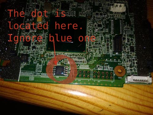
The SPI flash chip is on the front of the board once the main board is free:
Here is the location of the chip. On some models the orientation dot marking pin 1 may be misleading — the correct dot is just black.
Note: See the SPI Programmer Best Practices for programmer recommendations (Tigard recommended; CH347F preferred budget option; CH341A rev1.6+ acceptable with a physical selector).
Preparing the ROM
First download or build the maximized board ROM for the T420 and verify its hash. Since the T420 uses a single 8 MB flash chip, no ROM splitting is needed — the full heads-t420-maximized.rom is written directly to the single chip.
Flashing
Use [flasher] (flashrom or flashprog – see Tool Interchangeability) to create a backup, verify, then write the Heads ROM. See the Libreboot guide linked above for chip location and [flasher] command examples.
You should then follow through with configuring keys.